
Introduction
In the word puzzle game, a single misplaced letter can turn “TOLERANCE” into a meaningless string, resulting in failure. In the real world of engineering, a slight misinterpretation of the concept of “tolerance” or a minute lapse in dimensional control during manufacturing has consequences far beyond losing a game. It can lead to costly prototype scrap, critical equipment failure, or delays across an entire product line. Whether spelling a word or manufacturing a part, the core challenge is the pursuit of absolute precision and respect for the governing “rules” — be it grammar or a drawing specification.
Many view manufacturing as a rough “metal-cutting” process, overlooking the underlying, puzzle-like logic and meticulous control of microscopic details. This article conducts a thought experiment, comparing a high-precision CNC milling operation to solving a three-dimensional, metallic “technical word puzzle.” We will see that every step — from interpreting the complex “design language” (CAD model) and selecting the correct “alphabet” (tools and materials) to executing flawless “spelling paths” (toolpaths) on the “machine board” — demands the same focus, logic, and precision trained by word games.
Is a CAD File Just a Fancy 3D “Word Puzzle” Waiting to Be Solved?
This section establishes the core analogy, explaining how a CAD file functions as a complex, three-dimensional instruction set that must be “decoded” and executed with precision, much like solving a challenging puzzle.
1. The Blueprint as a Cryptographic Challenge
A 3D CAD model is not merely a picture; it is a dense, data-rich “cryptogram” for machinists. Like a word puzzle grid defines letter positions, the model defines the part’s final geometry, critical dimensions, and the allowable deviation for each — its tolerances. An engineer designing a complex assembly is effectively composing a long, technical sentence where every component is a “word” that must be spelled correctly and fit grammatically with its neighbors to ensure proper assembly and function.
2. The Rulebook: GD&T as the Authoritative Dictionary
To ensure everyone interprets the “puzzle” the same way, the industry relies on a universal standard: Geometric Dimensioning and Tolerancing (GD&T). Governed by standards like ASME Y14.5, GD&T is the definitive “grammar and dictionary” for engineering drawings. It provides a precise, symbolic language to communicate not just size, but also form, orientation, and location of features. Mastering this language is the first step in ensuring the manufactured part solves the design puzzle correctly.
3. The Role of the Machinist as Cryptographic Solver
The CNC machinist, equipped with CAM software, acts as the expert puzzle-solver. Their task is to interpret the GD&T clues, understand the spatial relationships between features, and devise a plan to physically realize the design. A missed datum reference or a misinterpreted profile tolerance is akin to misreading a clue, guaranteeing a failed outcome. To gain a deep, systematic understanding of how to “decode” and realize such complex designs, this comprehensive guide on CNC milling services provides a complete perspective from principles to practice.
Choosing Tools & Materials: Are You Picking the Right “Alphabet” for Your Metal “Word”?
This section extends the analogy to tooling and materials, arguing that selecting the correct cutting tools and workpiece material is as fundamental as choosing the right letters to form a word, directly impacting the feasibility and quality of the outcome.
1. The Material: The “Canvas” Defines the “Medium”
Just as you wouldn’t use a crayon on a whiteboard, you must match the tooling to the material. Aluminum 6061 is a common, malleable “canvas,” allowing for high-speed machining with sharp, positive-rake tools. Stainless steel 316 or titanium, however, are tougher “mediums.” They demand a completely different “alphabet”: tools made from ultra-hard materials like carbide with specialized coatings, running at lower speeds and feeds to manage heat and tool wear. Choosing the wrong material-tool combination is a fundamental error before the “spelling” even begins.
2. The Cutting Tools: A Precision “Character Set”
End mills, drills, and boring tools are the individual “characters.” A ball-nose end mill is used for sculpting complex 3D contours, while a chamfer mill creates angled edges. Selecting a tool with the wrong diameter, number of flutes, or coating for the operation is like trying to spell a word with the wrong letters — it may look approximately correct but will fail under scrutiny. The precision and wear resistance of these tools are the literal cutting edge of the manufacturing vocabulary.
3. The Cost of a Poor Selection
An incorrect tool or material choice manifests as a “spelling error” on the part: excessive tool wear, poor surface finish, chatter marks, or catastrophic tool breakage. These errors consume time and money, forcing a restart. A deep understanding of the interplay between material properties and tool geometry is what separates a basic machine operator from a skilled manufacturing linguist capable of precision CNC milling.
The CAM Program: How Does a Machine “Spell” a Path in Three Dimensions?
This section demystifies Computer-Aided Manufacturing (CAM) programming, describing it as the process of writing meticulous, step-by-step instructions that guide the cutting tool to “trace” or “spell” the part’s shape in physical space.
1. Writing the Instruction Set: From CAD to G-Code
The CAM programmer’s role is to translate the static 3D puzzle (CAD) into a dynamic set of motions. Using CAM software, they define the toolpaths — the precise routes the cutting tool will follow. This involves specifying the order of operations (roughing, then finishing), the tool’s entry and exit points, cutting depth, and feed rate. The output is G-code, a numeric control language the CNC machine understands, which is the ultimate “spelling script.”
2. The Art of Multi-Axis “Cursive Writing”
For complex parts, simple 3-axis motion (moving in X, Y, Z) is insufficient. 5-axis CNC milling adds two rotational axes, allowing the tool to approach the workpiece from virtually any angle. Machining a complex item like a turbine blade with 5-axis technology is analogous to writing a word in elegant, continuous cursive without lifting the pen, maintaining optimal tool engagement and surface finish throughout the entire, complex geometry. This capability is essential for complex parts milling with organic shapes.
3. Simulation: The Critical “Proofreading” Step
Before any metal is cut, the CAM program undergoes rigorous virtual simulation. This software visualizes the entire machining process, checking for errors like tool collisions with the part or fixture, verifying that no material is left uncut, and ensuring efficient motion. It is the digital equivalent of proofreading a document, catching potential “typos” (programming errors) that would be catastrophic and expensive on the shop floor. Therefore, translating digital instructions into a perfect physical entity requires partnership with experienced CNC milling precision manufacturers who are fluent in this three-dimensional language.
What Happens When the “Tolerance” Letter is Out of Place? The High Cost of a Micron.
This section delves into the critical importance of tolerances, illustrating with tangible examples how a deviation smaller than a human hair can render a part useless and lead to systemic failures.
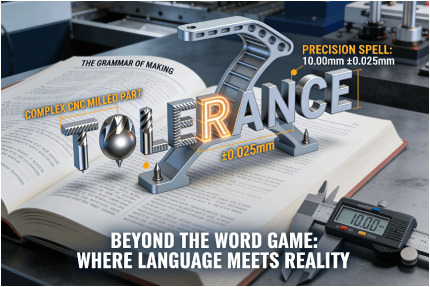
1. Defining the “Acceptable Misspelling”: In a word game, “TOLERANCE” must be spelled exactly. In manufacturing, a tolerance defines the permissible limit of variation. A dimension of 10.00 mm ±0.05 mm means the part is acceptable if it measures between 9.95 mm and 10.05 mm. This tiny band is the “acceptable misspelling.” However, exceeding it, even by a single micron (0.001 mm), means the part is out of specification — a failed puzzle.
2. The Domino Effect of a Failed Fit: Consider a simple shaft and bearing housing. The shaft diameter is specified as 10.00 mm +0.00/-0.02 mm (a shaft can be slightly smaller, but never larger). The housing bore is 10.00 mm +0.03/+0.01 mm. This creates a controlled clearance fit. If the shaft is machined at 10.01 mm (0.01 mm oversize) or the bore at 9.99 mm (0.01 mm undersize), the parts will not assemble, or will assemble with excessive force, leading to immediate damage. This is the real-world consequence of a tolerance training failure.
3. Systemic Quality as the “Spell Check”: Preventing such errors isn’t about hoping the machinist gets it right. It’s about systemized verification. Manufacturers adhering to ISO 9001 and IATF 16949 implement mandatory “spell-check” processes. This includes First Article Inspection (FAI) using a Coordinate Measuring Machine (CMM) to verify the first part against all dimensions, and Statistical Process Control (SPC) to monitor production and catch drifts before they create out-of-spec parts. This systemic approach ensures every “critical part” is “spelled” correctly.
From Prototype to Production: Can You “Copy-Paste” Precision a Thousand Times?
The final section addresses the challenge of scaling from a single, perfectly solved puzzle (prototype) to mass production, emphasizing that repeatable precision requires robust systems, not just skilled individuals.
1. The Challenge of Industrialized Consistency
Creating one perfect part proves a process is possible. Creating ten thousand identical perfect parts proves a process is controlled and repeatable. The transition requires moving from artisan skill to industrialized system. Factors like tool wear, machine thermal drift, and material batch variations must be systematically managed to ensure the 10,000th part is a true copy of the first.
2. The Systems that Enable “Copy-Paste”
Several systems work in concert:
l Standardized Work Instructions: Detailed, visual guides for operators eliminate variability.
l Tool Life Management: Tracking tool usage and replacing tools predictively before they wear and affect dimensions.
l Automated In-Process Inspection: Using on-machine probes to automatically check critical dimensions mid-run, allowing for real-time corrections.
3. The Ultimate Validation: Data-Backed Confidence
In high-volume production, confidence comes from data, not hope. A reputable manufacturer will provide inspection reports for sampled parts from each batch, demonstrating with CMM data that all critical dimensions are held within the specified tolerance bands. This transforms manufacturing from a black box into a predictable, engineering-driven process, whether for rapid CNC milling of prototypes or volume production. The discipline required mirrors the focus of skill-building games, but with infinitely higher stakes.
Conclusion
Whether arranging letters in the grid of a word puzzle or driving a cutting tool through the coordinate space of a CNC machine, the underlying principles are shared: an unwavering commitment to precision, logical process, and meticulous attention to detail. High-precision manufacturing is, at its heart, a linguistic art — translating abstract thought (design) into physical reality through a rigorous, rule-based syntax. Understanding this “grammar of making” not only fosters a deeper appreciation for the精密产品 around us but also reveals the foundational pillar of modern industrial civilization: an unshakeable commitment to getting it “right,” down to the last micron.
FAQs
Q: What’s a typical lead time to get a small, precise metal part CNC milled?
A: For a simple, small metal part, lead times for prototyping can be as fast as 1-3 business days, including programming and shipping. For more complex geometries, 5-7 business days is common. Providing a clear 3D model upfront is key to getting an accurate timeline.
Q: How do I know if my design is suitable for CNC milling or if it’s too complex?
A: A good rule is: if a feature can be reached by a rotating cutting tool, it can likely be milled. Deep internal pockets with small openings or extreme undercuts are challenging. The best method is to use a service offering a free Design for Manufacturability (DFM) analysis, which will highlight potential issues.
Q: What does “tight tolerance” like ±0.025mm really mean in practical terms?
A: It means the final part dimension must fall within a total range of 0.05mm (about half a human hair’s thickness). Holding this consistently requires high-end machines, perfect calibration, temperature control, and expert operators. It’s the difference between a perfect fit and a failure.
Q: Is CNC milling only for making one-off prototypes?
A: Not at all. While perfect for prototypes, CNC milling is excellent for low to medium-volume production (from tens to thousands of parts). It avoids the high cost of hard tooling (e.g., for injection molding) and allows for design flexibility between batches.
Q: How is the quality of a CNC milled part checked and verified?
A: Quality is verified using precision tools like Coordinate Measuring Machines (CMMs). These create a 3D map of the part and compare it to the original CAD model. Reputable manufacturers provide digital inspection reports with this data as proof that all tolerances are met.
Author Bio
This article is based on extensive experience in transforming complex theories into reliable hardware within the precision manufacturing realm. As a manufacturing partner certified to ISO 9001, IATF 16949, and AS9100D, LS Manufacturing specializes in interpreting the most intricate “design puzzles” and translating them into batch-after-batch precision reality. Intrigued by the art of precision making? Upload your CAD file today for a complimentary “Manufacturability and Precision Assessment Report” to see how your idea can be accurately “spelled” into reality.